
Back to Table of Contents
If you are using a shared IRQ or non-UART serial card, you should skip this
section and go to the section on 'Using a Shared IRQ or Non-UART Serial Card'.

If you are using an internal modem, note that all references to serial boards
are the same as referring to an internal modem.  Also note that most internal
modems only have support for up to 4 different IRQ's and I/O addresses.

Prior to installing your serial board, you should insure that neither the IRQ
or the I/O address of any of the ports on the board are being used by any other
devices in your system.  Following is a list of IRQ's and I/O addresses which
are commonly used by devices (those marked with a minus sign (-) may never be
used by a serial board):

		  Device		  IRQ	  I/O Address
		  ----------------------  ---	  -----------
		 -Timer 		   0	   040 - 05F
		 -Keyboard Controller	   1	   060 - 06F
		 *EGA/VGA Cards 	   2
		  Serial Port 2 	   3	   2F8 - 2FF
		  Serial Port 1 	   4	   3F8 - 3FF
		  Parallel Port 2	   5	   278 - 27F
		  Floppy Drive		   6	   3F0 - 3F7
		  Parallel Port 1	   7	   378 - 37F
		 -Real Time Clock	   8	   070 - 07F
		 *Same as IRQ 2 	   9
		 -Co-processor		  13	   0F0 - 0F1
		  Fixed Disk Controller   14	   1F0 - 1F8

	*NOTE: IRQ's 2 and 9 may never be used at the SAME time.

The following are suggested IRQ and I/O address settings for using up to 8
serial ports:

		      Device		      IRQ     I/O
		      ----------------------  ---     ---
		      Serial Port 1	       4      3F8
		      Serial Port 2	       3      2F8
		      Serial Port 3	       5      3E8
		      Serial Port 4	       2      2E8
		      Serial Port 5	      10      1F8
		      Serial Port 6	      11      1E8
		      Serial Port 7	      12      1A8
		      Serial Port 8	      15      2A8

An additional 2 serial ports may be added using the following IRQ and I/O
addresses:

		      Device		      IRQ     I/O
		      ----------------------  ---     ---
		      Serial Port 9	       7      400
		      Serial Port 10	      14      408

Refer to the documentation provided by the manufacturer of your particular
serial board for information on how to select IRQ and I/O addresses.

After you have the ports on your serial board set up to fit your system
requirements, you should write down the IRQ and I/O address information for
future reference.  Once you have determined the IRQ and I/O address that each
node on your system will use, you must run the SCFG program and go to the
Nodes->Node #->Modem Configuration and set the COM Port, UART IRQ Line, and
UART I/O Address.  Each node, when running on the same machine, should have a
unique COM Port number.

Notes on UARTs

If you are using an external high-speed modem, you may require a buffered
UART chip on your serial board for error-free transmissions. 8250 and 16450
UARTs DO NOT have buffers and are usually insufficient for high-speed modems.
16550AFN UARTs have a 16 byte FIFO UART which allows error-free transmissions
with high-speed modems, particularly necessary when multi-tasking. Almost
all internal high-speed modems come with a built-in 16550 UART.
If you are using a serial card which allows the use of shared IRQ's or has a
non-standard UART interface, you will need to use a device driver to interface
this card with Synchronet. Usually, such a driver would be included with the
serial card from the manufacturer. Third party drivers are also available (such
as COMM-DRV and X00).

Synchronet supports three driver interfaces, all using Int 14h services. The
supported driver interfaces are:

	FOSSIL (Fido/Opus/SEAdog Standard Interface Layer Version 5)
		Functions 0 through 6, and Fh
		Example FOSSIL drivers: X00, BNU, and COMM-DRV

	PC BIOS
		Functions 0 through 3

	PS/2 BIOS
		Functions 1, 2, 4, and 5

	DigiBoard
		DigiCHANNEL PC/Xi and PC/Xe DOS driver

When setting the COM port in SCFG->Nodes->Node #->Modem Configuration, you
will be prompted for the COM port type:
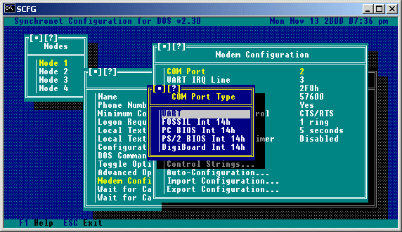 If you are NOT using a special shared IRQ or non-UART serial card, then you
should select "UART" and ignore the rest of this section.
When selecting a non-UART COM port type, the "Channel" will automatically be
set to the COM port number minus one. This is the zero-based COM port that will
be used when communicating with the device driver (i.e. COM port 1 is channel
0, port 2 is channel 1, etc). You should NOT change the channel number unless
you have a specific reason for doing so and understand exactly what you are
doing.
If you are using an Intelligent DigiBoard and are using the DigiBoard supplied
device driver, then select "DigiBoard Int 14h".
If the card you are using has a FOSSIL compatible device driver, this should
be your preferred selection unless you wish to use baud rates greater than
38400, in which case a "PS/2 BIOS" compatible driver would be a better choice.
The COMM-DRV/Universal Serial Communications Driver supports both FOSSIL and
PS/2 BIOS interfaces.
You should only select "PC BIOS" in a last case scenario (i.e. Your card's
device driver does not support any other Int 14h interface). The PC BIOS
interface does not support DTR, so if you use such a limited driver, you must
set "Drop DTR to Hang Up" to "No" under "Modem Toggle Options", set the
"Hang Up String" to "~~~\1\1\1~~~ATH" and change "S2=128" to "S2=1" in your
"Initialization String".
Int 14h drivers can also be used to communicate with non-UART serial devices
such as Packet Assembler/Disassemblers (PADs), Network Redirectors, HAM Radio
Packet Servers, etc.
If you are connecting a Synchronet node to another computer or terminal through
a serial port WITHOUT the use of a modem, you must set SCFG->Nodes->Node #
->Modem Configuration->Toggle Options->Dumb Modem Connection to "Yes". This
disables all modem commands (Init, Special Init, Answer, Off-hook, etc.) and
causes Synchronet to only log a user on when the DCD serial line is raised.

If your serial connection or terminal does not support the correct use of the
DCD line, then you must run SBBS with the 'D' command line switch to force
Synchronet to assume that DCD is always high. If this is the case, then there
is no way to "hang up" on the BBS.
Now that you've set up your serial card, the easiest way to finish setting up
the rest of the options for your modem is to run the SCFG program and go to the
Nodes->Node #->Modem Configuration->Auto-Configuration, and select your modem
model from the list of available choices.  If your modem is not listed, you may
select Generic 2400 for unlisted 2400bps Hayes compatible modems, Generic 9600,
Generic 14400, or Generic 28800 for unlisted high speed modems.  You may also
import .MDM configuration files (located in your control directory) if you
receive an updated or new version of a configuration file for your modem from
Digital Dynamics or a third party.

Following is a list of remaining options and a brief description of each for
those of you that wish to manually alter the modem settings.

UART (DTE) Rate is the data transfer rate between your computer and your modem,
for non-data-compressing, non-high-speed modems, you should set this to your
modem's highest DCE rate (e.g. a 2400bps modem should use a 2400bps DTE rate).
If you have a data-compressing or high-speed modem, this value should be set
to the highest DTE rate your modem supports (consult your modem manual).  If
you plan on using a FOSSIL driver for any external programs or doors, the
DTE rate you set for your FOSSIL driver should be the same number you use for
this option.

Hardware Flow Control should be set to Transmit and Receive (Both) if your
modem supports CTS/RTS hardware flow control (usually data-compressing or
high-speed modems).

Answer delay is the number of seconds to pause after a connection is
established and before the terminal detection string is sent. It is suggested
that this delay be set to a minimum of 5 seconds to allow for accurate
terminal type detection. If the callers on your BBS are experiencing
inaccurate terminal type detection, you may want to increase this number.

Answer after (# rings) is the number of rings the bbs should wait for before
answering the phone, the minimum is 1 ring.

Reinitialization Timer is used to automatically reinitialize the modem
periodically to make sure it is functioning correctly.	If you find that your
modem works most of the time, but occasionally will not answer the phone or
functions incorrectly, you may wish to use this feature.  Setting this value to
0 will disable periodic modem reinitialization.

Example (for Generic 28.8k Modem on COM 2):
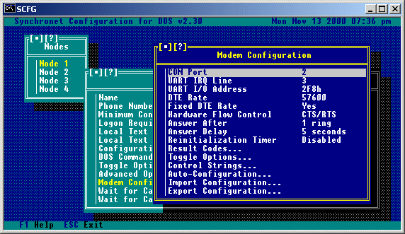
Result Codes is a list of numeric result codes (connect codes) supported by
your modem. If you have set "Use Verbal Result Codes" to 'Yes' in your
the SCFG modem toggle options for this node, this list is not used.

You would use this list to add result codes that your modem supports, but are
not currently in the list or to remove codes that are in the list but are not
supported by your modem.  For each result code, the actual numeric code, the
DCE (connect) rate, estimated file transfer CPS, and an 8 character description
of the connection type are stored. A complete list of result codes supported by
your modem should be given in your modem manual.

Here is an example of what the result code list would look like for a Generic
28.8k modem:
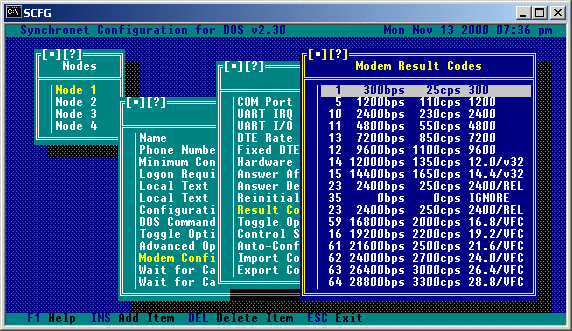
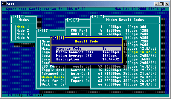
Selecting result code 15 from this menu would result in a sub-menu as follows:
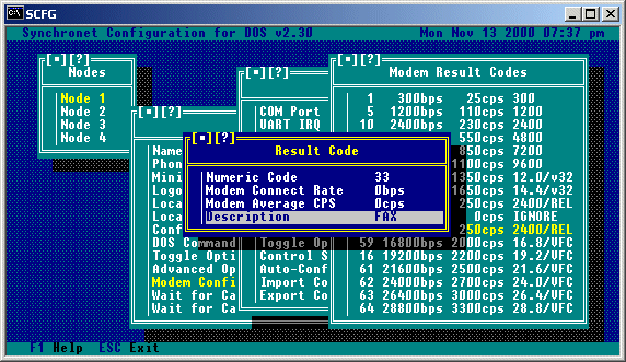
 If "FAX" is used for the result code description, Synchronet will exit with
an error level of 100 when this result code is returned. This feature is used
for FAX/Modems that can auto-detect FAX and DATA calls and return a numeric
result code for FAX connections. If a different error level is preferred,
use "EXIT nnn" (where nnn is a numeric value) for the description. If a verbal
"FAX" or "+FCON" result code is returned, Synchronet automatically exits with
an error level of 100 (see FAX/Modem setup later in this chapter).
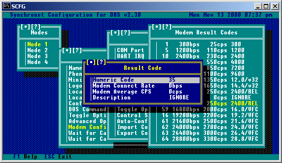
If your modem returns any result codes PRIOR to the actual connection result
code (and this behavior cannot be disabled), then add these result codes to the
result code list and enter "IGNORE" for the result description, thus causing
Synchronet to ignore this result code and wait for another result code to
determine the actual connection type. This step is only necessary for modems
that insist on returning multiple result codes during a connection.
Selecting this option gives a menu of available modem toggle options:
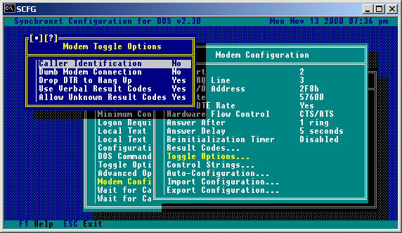 Caller Identification:
This is used for toggling the ability to use Caller-ID. Consult the
section on caller identification for more information.
Dumb Modem Connection:
This option should be set to 'Yes' if you are using a dumb (null) modem
cable to connect a computer to your BBS.
Drop DTR to Hang Up:
This is normally set to 'Yes', but some modems do not support the
dropping of DTR to hang up the modem. If your modem is one of those,
you should toggle this option to 'No'.
Use Verbal Result Codes:
This option should be set to 'Yes' for the easiest configuration of
your modem. When this option is set to 'Yes', SBBS will automatically
parse the CONNECT message received by the modem to determine the
connect (DCE) rate and estimated CPS of the call. If "ARQ", "V42",
"LAPM", "MNP", or "REL" are contained in the connect string, hardware
error correction is assumed to be in effect and the estimated CPS
rate is increased appropriately. Setting this option to 'Yes' has the
added advantage of allowing DCE rates above 64000. Result codes not
recognized as CONNECT messages (e.g. PROTOCOL, CARRIER, etc) are
ignored. Result codes with "FAX" or "+FCO" cause SBBS to exit with an
error level of 100 (for the execution of FAX receive software).
Allow Unknown Result Codes:
If "Use Verbal Result Codes" is set to 'No', then numeric result codes
returned by the modem are then looked up in the configured result code
list. If the result code is not found and the "Allow Unknown Result
Codes" option is set to 'No', the call is immediately disconnected and
an error message is logged for the sysop's attention. If the result
code is not found and the "Allow Unknown Result Codes" option is set to
'Yes', then the connection information (DCE rate, estimated CPS rate,
etc) is taken from the last configured result code and an error message
is still logged for the sysop's attention.
Modem Control Strings are the strings which are sent to your modem at various
times during BBS operation.  Normally the default strings are sufficient for
proper operation, but occasionally you may wish to modify one or more of these
settings.
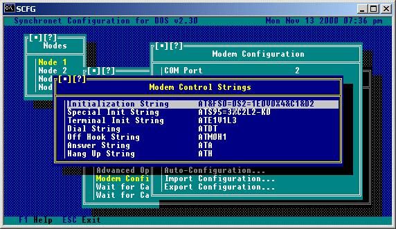 Initialization String is the basic modem initialization for Synchronet. You
should not modify this unless you are unhappy with any of the settings and are
familiar enough with the AT command set to understand what each command does.
Placing a tilde '~' anywhere in this string will produce a 500 millisecond
(half second) pause. Synchronet requires that the modem NOT echo characters
back and return numeric result codes. So "E0" and "V0" must be included
in the init string. Since Synchronet manually detects incoming calls from
the modem, the modem's auto-detect feature must be disabled with "S0=0". If
you do not want to hear the connection progress sounds, add "M0" to the end
of your modem initialization string to disable the modem's speaker.
Special Init String is where additional initialization commands are placed for
specific modem types, usually error-correcting, data-compressing, or high-speed
modems.
Terminal Init String is the initialization string sent to the modem when you
enter Synchronet's terminal mode ('T' from the waiting for call screen).
Dial String is the command sent to the modem for making outbound calls.
Currently only used by the Synchronet Callback Verifier.
Off Hook String is the command sent to the modem to take the phone off-hook
(busy).
Answer String is the command sent to the modem when a ring is detected by
Synchronet.
Hang Up String is the command sent to the modem to hang up the phone and is
only used if Drop DTR To Hang Up modem toggle option is set to No.
The auto-configuration contains a very long list of modem types.  Using this
list is the EASIEST way to configure your modem to work with Synchronet.  All
you need to do is select your modem from this list and most everything will be
configured for you.  If you do not see your modem in this list, you can
normally select a 'Generic' model from the list.

If someone later creates an .MDM configuration file specifically for your
modem, you can use this configuration file simply copying the .MDM file into
your control directory and then selecting the 'Import Configuration' option
from the menu and typing in the name of the .MDM file.

If you create a new configuration you would like to make available to people,
you can export the configuration information into an .MDM file by selecting the
'Export Configuration' option from the menu.
If your modem supports one of the Caller-ID formats listed below and you have
Caller-ID service enabled on your phone line, you can have Synchronet log
Caller-ID information and disallow specific numbers. First, add the appropriate
commands to SCFG->Nodes->Node #->Modem Configuration->Special Init String to
enable Caller-ID on your modem (see your modem's manual for details). Then set
SCFG->Nodes->Node #->Modem Configuration->Toggle Options->Caller Identification
to "Yes".

If you are using a Front-End (e.g. FrontDoor) on your BBS, the CID information
can be passed to Synchronet on the SBBS command line with the 'Z' command line
switch (e.g. sbbs c14400 z01-09_11:15_7145295313). The Caller-ID information
must be ONE string with no spaces.

The user's phone number will be placed in the user's note field for your
records and logged for each call in the system log. If you wish to disallow
access for a specific number, create the file CID.CAN in your TEXT directory
and enter one phone number per line to disallow that number. If you want a
message to be displayed to the user who calls with a disallowed number, create
the message file BADCID.MSG in your TEXT directory.

Supported formats:

	Single Line:

		MM-DD HH:MM Number

	Three Line:

		TIME:
		CALLER NUMBER:
		CALLER NAME:

	Four Line:

		DATE =
		TIME =
		NMBR =
		NAME =
In order for Synchronet to be able to receive incoming FAXes, there are a few
requirements that must be met, these are:

	1) Your modem MUST be able to return either a verbal or numeric FAX
	   result code (verbal results must contain "FAX" or "+FCO").

	2) Your modem MUST be able to auto-detect FAX and DATA calls.

	3) You MUST have a command line receive FAX program that works with
	   your FAX modem.

If all of the above requirements can be met, then you will need to modify the
SBBS.BAT/SBBS.CMD file in the directory of the node(s) to be used for receiving
incoming FAXes as follows (using a ZyXEL FAX/Modem setup on COM 2 as an
example):

-----------------------------------[ Begin ]-----------------------------------
@echo off
:top
..\exec\sbbs %1 %2 %3 %4 %5
if not errorlevel 100 goto end
c:
cd \zfax
rcvfax 2 /p:1
echo Incoming FAX! >> c:\sbbs\data\msgs\0001.msg
c:
cd \sbbs\node1
goto top
:end
------------------------------------[ End ]------------------------------------

Change the 'c:' on the 5th line to the drive letter where your receive FAX
program resides.

Change the 'cd \zfax' on the 6th line to the name of the directory where your
receive FAX program resides.

Change the 'rcvfax 2 /p:1' on the 7th line to match the name and command line
options of the receive FAX program for your modem.

Change the 'c:\sbbs\data' portion of the 8th line to match the location of your
Synchronet data directory.

Change the 'c:' on the 9th line to the drive letter where you have Synchronet
installed.

Change the 'cd \sbbs\node1' on the 10th line to match the directory of the
node(s) that will be set up for receiving FAXes.

Check your modem manual to find out if your modem responds with a verbal
"FAX" (e.g. ZyXEL) or "+FCO" (e.g. Practical Peripherals) result code or a
numeric FAX result code (e.g. Hayes). If a numeric result code is returned,
then run SCFG from your node directory and go to Nodes->Node #->Modem
Configuration->Result Codes and add the numeric result code your modem returns
for a FAX connect and enter "FAX" for the result description. If your modem
returns a numeric "DATA" result code when in auto-detection mode (e.g. Hayes)
then add this result code to your result code list in SCFG and enter "IGNORE"
for the result description.

Example numeric FAX result code (using Hayes Optima 288):
 Example numeric DATA result code (using Hayes Optima 288):
 If there are any commands needed to enable FAX auto-detection, add these
commands to the end of your Special Init string in SCFG->Nodes->Node #->Modem
Configuration. If there is an auto-configuration entry listed for your modem
with FAX enabled, this step is not necessary.
Now you are ready to receive FAXes! When your modem returns a FAX result code
to Synchronet, the receive FAX program specified in this batch file will be
executed. FAXes will be placed into the directory that your FAX program uses
for received FAXes.
FAXes CANNOT be sent to specific users on the BBS, this option is only for the
convenience of being able to receive FAXes without the need of a dedicated FAX
machine and phone line. However, the ability to allow users to FAX on demand
or to upload files to be sent out as FAXes can be accomplished by using one of
the add-ons (Domain FAX) from Domain Entertainment.
Back to Top
Copyright © 2000 by Rob Swindell
Synchronet BBS Software (Synchronet)
Version 3 is comprised of several documentation,
library, executable, and source code
files, all of which are covered by the
GNU General Public License with the exception of the following portions
covered by
the GNU Lesser General Public License:
SMBLIB and XSDK.
Synchronet Version 2 (for DOS and OS/2) and its source code was released to the
Public Domain by Digital Dynamics
in 1997 and remains Public Domain software today.
Synchronet Version 3 is not Public Domain software.
Rob Swindell
PO Box 501
Yorba Linda, CA 92885
http://www.synchro.net
For the complete Copyright Information please
read the Copyright Documentation
.
 If you are NOT using a special shared IRQ or non-UART serial card, then you
should select "UART" and ignore the rest of this section.
When selecting a non-UART COM port type, the "Channel" will automatically be
set to the COM port number minus one. This is the zero-based COM port that will
be used when communicating with the device driver (i.e. COM port 1 is channel
0, port 2 is channel 1, etc). You should NOT change the channel number unless
you have a specific reason for doing so and understand exactly what you are
doing.
If you are using an Intelligent DigiBoard and are using the DigiBoard supplied
device driver, then select "DigiBoard Int 14h".
If the card you are using has a FOSSIL compatible device driver, this should
be your preferred selection unless you wish to use baud rates greater than
38400, in which case a "PS/2 BIOS" compatible driver would be a better choice.
The COMM-DRV/Universal Serial Communications Driver supports both FOSSIL and
PS/2 BIOS interfaces.
You should only select "PC BIOS" in a last case scenario (i.e. Your card's
device driver does not support any other Int 14h interface). The PC BIOS
interface does not support DTR, so if you use such a limited driver, you must
set "Drop DTR to Hang Up" to "No" under "Modem Toggle Options", set the
"Hang Up String" to "~~~\1\1\1~~~ATH" and change "S2=128" to "S2=1" in your
"Initialization String".
Int 14h drivers can also be used to communicate with non-UART serial devices
such as Packet Assembler/Disassemblers (PADs), Network Redirectors, HAM Radio
Packet Servers, etc.


 If "FAX" is used for the result code description, Synchronet will exit with
an error level of 100 when this result code is returned. This feature is used
for FAX/Modems that can auto-detect FAX and DATA calls and return a numeric
result code for FAX connections. If a different error level is preferred,
use "EXIT nnn" (where nnn is a numeric value) for the description. If a verbal
"FAX" or "+FCON" result code is returned, Synchronet automatically exits with
an error level of 100 (see FAX/Modem setup later in this chapter).
If your modem returns any result codes PRIOR to the actual connection result
code (and this behavior cannot be disabled), then add these result codes to the
result code list and enter "IGNORE" for the result description, thus causing
Synchronet to ignore this result code and wait for another result code to
determine the actual connection type. This step is only necessary for modems
that insist on returning multiple result codes during a connection.
 Caller Identification:
This is used for toggling the ability to use Caller-ID. Consult the
section on caller identification for more information.
Dumb Modem Connection:
This option should be set to 'Yes' if you are using a dumb (null) modem
cable to connect a computer to your BBS.
Drop DTR to Hang Up:
This is normally set to 'Yes', but some modems do not support the
dropping of DTR to hang up the modem. If your modem is one of those,
you should toggle this option to 'No'.
Use Verbal Result Codes:
This option should be set to 'Yes' for the easiest configuration of
your modem. When this option is set to 'Yes', SBBS will automatically
parse the CONNECT message received by the modem to determine the
connect (DCE) rate and estimated CPS of the call. If "ARQ", "V42",
"LAPM", "MNP", or "REL" are contained in the connect string, hardware
error correction is assumed to be in effect and the estimated CPS
rate is increased appropriately. Setting this option to 'Yes' has the
added advantage of allowing DCE rates above 64000. Result codes not
recognized as CONNECT messages (e.g. PROTOCOL, CARRIER, etc) are
ignored. Result codes with "FAX" or "+FCO" cause SBBS to exit with an
error level of 100 (for the execution of FAX receive software).
Allow Unknown Result Codes:
If "Use Verbal Result Codes" is set to 'No', then numeric result codes
returned by the modem are then looked up in the configured result code
list. If the result code is not found and the "Allow Unknown Result
Codes" option is set to 'No', the call is immediately disconnected and
an error message is logged for the sysop's attention. If the result
code is not found and the "Allow Unknown Result Codes" option is set to
'Yes', then the connection information (DCE rate, estimated CPS rate,
etc) is taken from the last configured result code and an error message
is still logged for the sysop's attention.
 Initialization String is the basic modem initialization for Synchronet. You
should not modify this unless you are unhappy with any of the settings and are
familiar enough with the AT command set to understand what each command does.
Placing a tilde '~' anywhere in this string will produce a 500 millisecond
(half second) pause. Synchronet requires that the modem NOT echo characters
back and return numeric result codes. So "E0" and "V0" must be included
in the init string. Since Synchronet manually detects incoming calls from
the modem, the modem's auto-detect feature must be disabled with "S0=0". If
you do not want to hear the connection progress sounds, add "M0" to the end
of your modem initialization string to disable the modem's speaker.
Special Init String is where additional initialization commands are placed for
specific modem types, usually error-correcting, data-compressing, or high-speed
modems.
Terminal Init String is the initialization string sent to the modem when you
enter Synchronet's terminal mode ('T' from the waiting for call screen).
Dial String is the command sent to the modem for making outbound calls.
Currently only used by the Synchronet Callback Verifier.
Off Hook String is the command sent to the modem to take the phone off-hook
(busy).
Answer String is the command sent to the modem when a ring is detected by
Synchronet.
Hang Up String is the command sent to the modem to hang up the phone and is
only used if Drop DTR To Hang Up modem toggle option is set to No.
 Example numeric DATA result code (using Hayes Optima 288):
 If there are any commands needed to enable FAX auto-detection, add these
commands to the end of your Special Init string in SCFG->Nodes->Node #->Modem
Configuration. If there is an auto-configuration entry listed for your modem
with FAX enabled, this step is not necessary.
Now you are ready to receive FAXes! When your modem returns a FAX result code
to Synchronet, the receive FAX program specified in this batch file will be
executed. FAXes will be placed into the directory that your FAX program uses
for received FAXes.
FAXes CANNOT be sent to specific users on the BBS, this option is only for the
convenience of being able to receive FAXes without the need of a dedicated FAX
machine and phone line. However, the ability to allow users to FAX on demand
or to upload files to be sent out as FAXes can be accomplished by using one of
the add-ons (Domain FAX) from Domain Entertainment.